To start using Persistent Micelle Templates, you are going to need to be able to coat substrates under controlled humidity conditions. Commercial spin coaters with temperature and humidity control cost a lot of $$$. On the other hand, the cheapest approach of attaching your sample to a computer fan with double-stick tape leaves much to be desired. Our home built setup includes most of the best features from commercial spin coaters (vacuum chuck, set speed & time, speed ramps, humidity/solvent & temperature control) at a fraction of the cost.
Meet our spin coater:
The core components are:
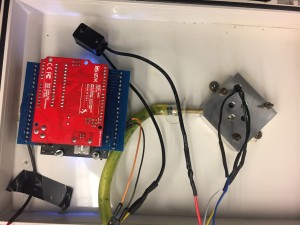
- Arduino Uno controller with push button LCD screen and breakout board
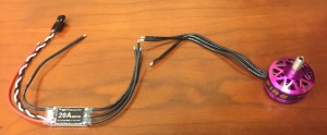
- A rotor motor from a quadcopter. Get one with a hollow shaft so it is easier to make the vacuum chuck. We used a 2600 kV motor, but I suggest trying a <1900 kV.
- A bubbler setup with a hot plate to produce air with controlled humidity and temperature
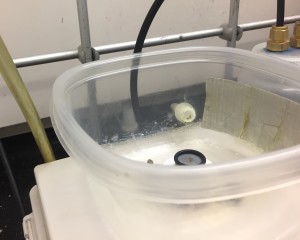
- Tupperware enclosure for the spin coating environment. We like the Gladware variety.
Other bits include:
- Electronic speed controller (ESC)
- ESC Programming Interface, recommended though not required
- RPM sensor
- Enclosure
- Spare computer power supply
- Solenoid valve, 2 hose adapters
- Switches for power and vacuum
- Corrosion-X, a corrosion-inhibiting lubricant
- Heat shrink tubing, electrical tape, resistors, switches, soldering iron
- Capacitor to minimize voltage fluctuations
Do-It-Yourself Instructions:
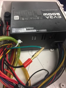
Power. Most of the spin coater components will need electricity. Here, an old computer power supply is perfectly suitable for the 5 V needed for the Arduino and LCD screen as well as the 12 V needed for the ESC and the solenoid valve. You can clip the green wire to any black wire to turn the power supply on and off. This will be need to be cycled any time the power supply turns off due to excessive current. This is quite reliable for us, though it would have been a better idea to add a capacitor on the 12V leads to the ESC to regulate the voltage. You can figure out which wires are needed for each voltage by googling “ATX pinout diagram.”
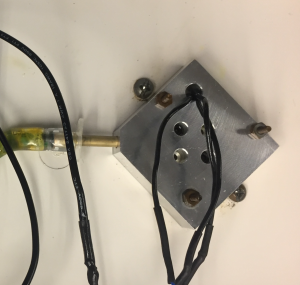
Vacuum. The solenoid valve controls the application of vacuum to the vacuum chuck. It is pictured just to the left of the power supply in the above photo. The setup here is straightforward by tapping into the 12 V power lines with a toggle switch. A tube connects from the solenoid valve outside of the enclosure to your house vacuum. A separate tube connects the other end of the solenoid valve to the back of the rotor. Our machine shop made a nice little mounting plate to direct the vacuum to the back side of the rotor. We have used hot glue in the past with similar success.
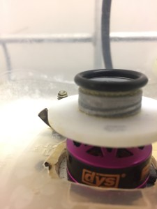
Motor. Our machine shop made a small teflon drip guard to keep liquids out of the motor. A nut with o-ring holds the splash guard to the bellhousing of the motor. That o-ring is important if you want to keep your samples from flying off! You can get away without the o-ring if you only coat small 1cm x 1cm wafer pieces at modest RPMs. The motor shaft of these DYS motors is mostly hollow and is almost a thru hole – we needed to drill out a few mm with a carbide bit so that the vacuum on the backside of the motor mount reaches up to the vacuum chuck and o-ring. This allows for clean and easy sample mounting without any double stick tape. I recommend removing the bell screw/clip since the magnets are plenty strong to hold the bell in place and you will need the bell detached for drilling sake anyways. If your bell is connected with a screw then you are going to need to heat the screw with a soldering iron so that the LockTite melts; otherwise you are going to strip the screw head – just ask how I know that… Be sure to generously coat the motor bell with Corrosion-X if you plan to use corrosive solutions.
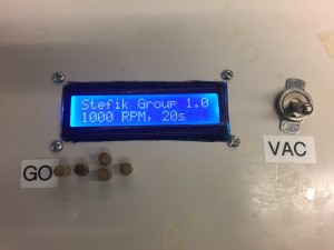
Arduino LCD Interface. Arduino makes this build relatively easy with cheap, off-the-shelf components. Here a ~$15 Arduino shield with LCD and push buttons handles user input and displays the status. The software runs on a ~$10 Arduino Uno. The code is provided below.
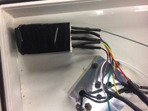
In terms of wiring, one side of the ESC is the inputs and the other the outputs. The input side has a big red and black wire and then 1-3 other smaller wires. The big red and black wire connect to the 12 V line of the power supply. Here the 12 V line from the power supply it is approximately equivalent to a “3S” battery, thus this 2S-4S rated ESC is fine. The small white wire is the signal wire for controlling the ESC speed, the small black wire is an optional signal ground both of these connect to the Arduino for setting the speed. I will be using a pulse-width modulation (PWM) signal from the Arduino to control the ESC speed, more on that later. If your ESC has a third wire then that is a 5V output for running other things: that is called a “battery elimination circuit” and is not needed in these plans. The other side of the ESC has 3 black wires, these connect to any 3 of the wires on the motor as pictured below.
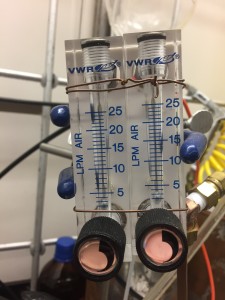
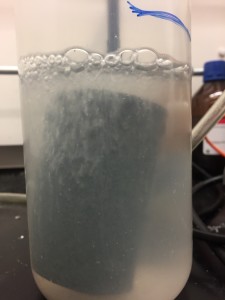
Humidity Control. A dual-flow controller setup provides for easy tuning of humidity. One line passes dry compressed air directly towards the sample chamber. The other line passes through a submerged aquarium stone to produce nearly-saturated vapor. The gas emerging from the bubbler is then mixed with the dry air and passed through a thermostated copper coil to maintain constant temperature and humidity. The mixing ratio of dry to wet air determines the humidity. Please note that some purge time is needed in between samples for the chamber to equilibrate to the desired humidity. The needed time is easily estimated with the Basic Room Purge Equation – here 1-2 min with 25 LPM of flow is plenty sufficient for a small tupperware.
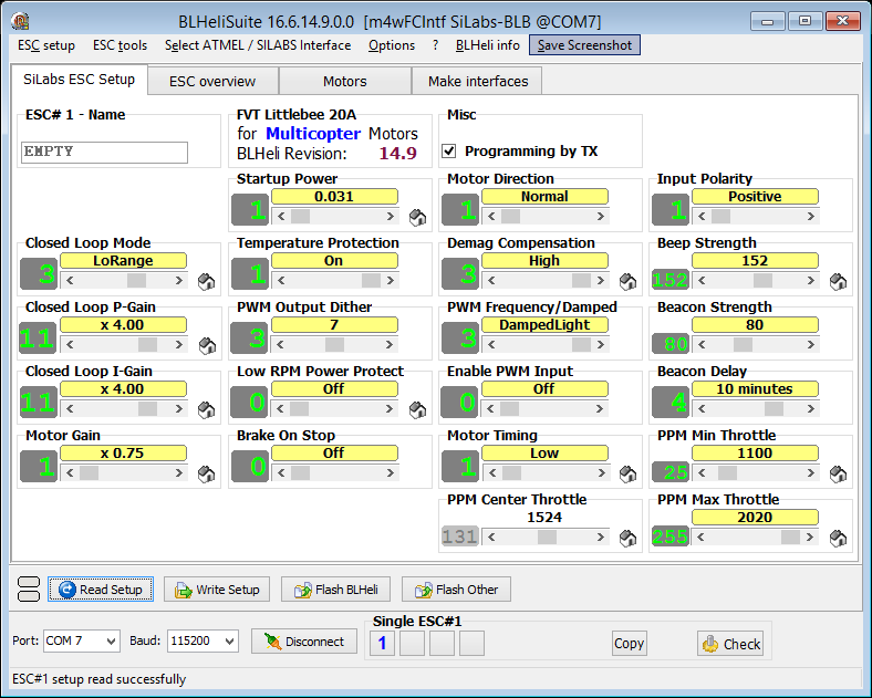
Speed Calibration. The ESC will likely need some adjustment before use. First, update the ESC to the latest firmware with the BLHeli Suite. In the settings, be sure to set the ESC to “closed Loop Mode,” that way it translates the input PWM signal to specific RPM targets and regulates the control with a PID loop. Typically the stop signal is ~1100 us and the maximum speed signal is ~2000 us. Use the Motors tab to then ramp your motor up and down in throttle. You can use a second Arduino board to monitor the rotor RPMs with an RPM sensor and some simple code, provided below. Be sure to use a 1k ohm resistor between the output of the RPM sensor and the Arduino input. Also note that the wire colors on the RPM sensor are counterintuitive – we normally change the code to the standard black for ground and red for 5V input. Adjust the “closed loop P-gain” and “closed loop I-gain” to get a smooth RPM response without oscillations (intro to PID tuning). Depending on your motor, you may also need to adjust the “Motor gain” and the “startup power.” (Intro to everything BLHeli)
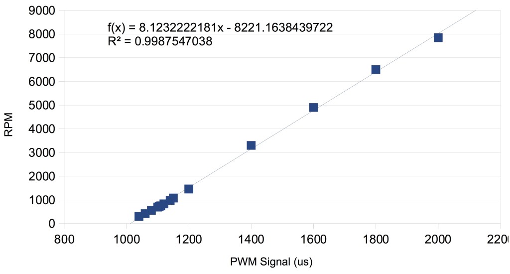
Once that is done, you will need to calibrate the ESC. This type of ESC has a lousy internal clock, so you the first thing needed is to calibrate the PWM signal relative to the Arduino output. Set the Arduino to output a 2000 us signal, apply power to the ESC and you will hear some musical chimes indicating the high-signal was recorded, quickly change the output to 1000 us and another musical chime will sound indicating the the low-signal was recorded (calibration tips). Power cycle the ESC to start it with the new settings. Next, use the first Arduino to send a series of PWM signals, ranging from 1020-2000us and record the resulting RPM values as read from the second Arduino using the RPM sensor (helpful notes). A simple graph should show a linear correlation of signal to RPM if the PID parameters are properly set.
Use the fit equation to calculate your the PWM signal needed for your target RPM values. After calibration, be sure to uncheck “Programming by TX” in the BlHeli Suite, or else you are one power glitch away from all that calibration going in the trash can. Seriously, you want that box unchecked.Humidity Calibration. A calibration chart should be made for the ratio of wet:dry air and the corresponding relative humidities. A linear trend is expected, however note that many hygrometers are not able to resolve <20%RH. Thus extrapolation is an option for low humidity targets after calibration at higher %RH.
Arduino code for RPM measurement (download right click and “Save Link As”):
Arduino code for Spin Coater with LCD screen (download right click and “Save Link As”):
#include <LiquidCrystal.h>
#include <Servo.h>
Servo myesc;
#define MAX_SIGNAL 2000
#define MIN_SIGNAL 500
#define ESC_PIN 13
// initialize the library with the numbers of the interface pins
LiquidCrystal lcd(8, 9, 4, 5, 6, 7);
//Key message
char msgs[5][15] = {“Right Key OK “,
“Up Key OK “,
“Down Key OK “,
“Left Key OK “,
“Select Key OK”
};
int adc_key_val[5] = {75, 250, 420, 620, 780 };
int adc_key_in;
int key = -1;
int oldkey = -1;
int speeds[] = {400, 500, 750, 1000, 1100, 1500, 2000, 3000, 4000, 5000, 7000};
int escvalues[] = {1093.9, 1106.1, 1136.7, 1167.2, 1179.4, 1228.2, 1289.3, 1411.4, 1533.5, 1655.6, 1899.8};
int times[] = {1, 1.5, 2, 5, 10, 20, 30, 45, 60, 120, 300, 600};
int speeds_size = sizeof(speeds) / sizeof(int) – 1;
int times_size = sizeof(times) / sizeof(int) – 1;
int selected_speed = 0;
int selected_time = 0;
String lyrics = “You spin me right round, wafer; Right round like a record, wafer; Right round round round; You spin me right round, wafer; Right round like a record, wafer; Right round round round “;
int lyrics_size = sizeof(lyrics) / sizeof(char) – 1;
void setup() {
Serial.begin(9600);
myesc.attach(ESC_PIN);
//myesc.writeMicroseconds(MAX_SIGNAL); //option to calibrate ESC
//delay(4000);
myesc.writeMicroseconds(MIN_SIGNAL);//start with motor off
Serial.println(“arming”);
lcd.begin(16, 2);// set up the LCD’s number of columns and rows:
lcd.setCursor(0, 0); lcd.print(“Stefik Group 1.0”);// Print a message to the LCD.
lcd.setCursor(0, 1); lcd.print(“you spin me”); delay(800);
lcd.setCursor(0, 1); lcd.print(“round like a “); delay(800);
lcd.setCursor(0, 1); lcd.print(“record now “);
delay(800); //hold the load screen
lcd.setCursor(0, 1); update_display();
}
void loop() {
//lcd.setCursor(0, 1);// set the cursor to column 0, line 1 (note: line 1 is the second row, since counting begins with 0):
adc_key_in = analogRead(0); // read the value from the sensor
key = get_key(adc_key_in); // convert into key press
if (key != oldkey) // if keypress is detected
{
delay(50); // wait for debounce time
adc_key_in = analogRead(0); // read the value from the sensor
key = get_key(adc_key_in); // convert into key press
if (key != oldkey) //a new button press is detected!
{
oldkey = key; //avoid phantom presses durring continuous hold
if (key == 0) //right key pressed
{
if (selected_time != times_size)
{
selected_time++;
}
}
if (key == 1) //up key pressed
{
if (selected_speed != speeds_size)
{
selected_speed++;
}
}
if (key == 2) //down key pressed
{
if (selected_speed > 0)
{
selected_speed–;
}
}
if (key == 3) //left key pressed
{
if (selected_time > 0)
{
selected_time–;
}
}
if (key == 4) //select key pressed
{
//take 1 second to spin up
int mystep;
int numberofsteps = 10;
int nextspeed;
for (mystep = 0; mystep < numberofsteps; mystep++) //take 100 incraments from slowest speed to requested speed
{
nextspeed = escvalues[0] + (escvalues[selected_speed] – escvalues[0]) * mystep / numberofsteps;
myesc.writeMicroseconds(nextspeed);//set the motor speed
Serial.println(nextspeed);
delay(1000 / numberofsteps);
}
myesc.writeMicroseconds(escvalues[selected_speed]);
Serial.println(“requested speed”);
int t; int cursorpos;
for (t = times[selected_time] – 1; t >= 0; t–) //continue spinning for [requested time minus spinup time]
{
cursorpos = (times[selected_time] – t) * 2;
lcd.setCursor(0, 0); lcd.print(lyrics.substring(cursorpos, cursorpos + 16));
delay(500);
cursorpos++;
lcd.setCursor(0, 0); lcd.print(lyrics.substring(cursorpos, cursorpos + 16));
lcd.setCursor(0, 1); lcd.print(“woosh! “);
lcd.setCursor(9, 1); lcd.print(t); lcd.print(“s”);
delay(500);
}
myesc.writeMicroseconds(MIN_SIGNAL);//turn off motor
}
update_display();
} //
} //new key pressed
} //overall loop
void update_display() {
lcd.setCursor(0, 0); lcd.print(“Stefik Group 1.0”);// Print a message to the LCD.
lcd.setCursor(0, 1);
lcd.print(speeds[selected_speed]);
lcd.print(” RPM, “);
lcd.print(times[selected_time]);
lcd.print(“s ” );
}
int get_key(unsigned int input) // Convert ADC value to key number
{ int k;
for (k = 0; k < 5; k++)
{
if (input < adc_key_val[k])
{
return k;
}
}
if (k >= 5)
k = -1; // No valid key pressed
return k;
}
This project was inspired by earlier works with spin coaters based on hard drive motors (article, video). That is actually what we built first, however our acidic solutions quickly ruined the aluminum hard drive motor. We have good reliability using rotor motors for 3 years now protected by Corrosion X. If a motor were to expire, they are easily replaced with identical parts available online with short notice. You might be able to get away by just swapping the motor bell, so be sure to order an identical spare to have on hand.
Please send a photo of your completed build:

Maciek Łojkowski, Warsaw University of Technology
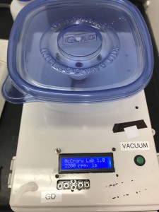
Taylor Soucy of McCrory Lab, University of Michigan
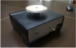
Jonas Bertels, KU Leuven University


